The receiver has 20 user programmable channels and has been set up for 5 satellite frequencies, 137.3 137.4, 137.5, 137.62 and 137.85 MHz. You can change them or add more at any time. There are many more environmental satellites in the 137-138 MHz band however due to budget cuts by the US and Russian governments there may be only one or two from each government presently operating. It's important to get the schedule from the satellite tracking program (included with most acquisition programs) or you could spend hours waiting for the satellites to come within range.
The first thing you must do is to check the programming. If the receiver has not been powered for about 30 days the frequency memory could be lost. Always plug in the wall plug power supply before turning the receiver on or off. To do otherwise could cause loss of memory. Turn the receiver on with the volume control switch and observe the front panel LCD screen. If the lower right bottom of the screen has the words "memory loss" and the frequency reads 0000000 you will have to re-program the receiver by following the instructions on the sheet titled "Programming the Vanguard Voyager II".
Unless there is a memory loss the receiver always returns were it was when last turned off. This being the case follow the following steps to make a test prior to connecting the antenna.
1. Check that the receiver volume control off-on is OFF (fully
counter clockwise).
2. Plug the wall plug power supply into a wall outlet.
3. Plug the free end of the power supply cable into receptacle on the
rear panel marked DC 13.8 Volts.
4. Turn the squelch control fully clockwise.
5. Turn the volume control up half way. This will also turn on the
receiver.
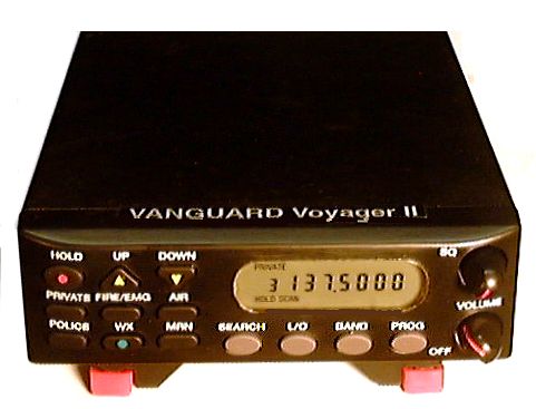
6. There should be a loud rushing noise which is normal and the LCD
screen should be backlit with a frequency displayed.
7. Adjust the volume to a comfortable level.
8. Press PRIVATE located on the left end of the front panel.
This will increment the channel number and a new frequency will be displayed.
9. Press PRIVATE repeatedly to check the frequency of the programmed
channels.
10. Turn the squelch control very slowly counter-clockwise until the
noise stops.
11. In 2 seconds the receiver enters SCAN mode. The words SCAN
scroll across the LCD screen. Since the antenna is not connected
it will scroll forever unless it picks up a strong interfering signal (as
from you computer).
12. Press SEARCH on the bottom left of the front panel. This
takes the receiver out of SCAN mode and puts it in SEARCH
mode.
13. SEARCH mode searches every frequency in the PRIVATE band,
not just the programmed ones and is the way to add new frequencies. Every
frequency is displayed as it searches.
14. Having made these tests you are now ready to connect the antenna.
If you are using the VANGUARD APT-2 the preamp at the antenna will
be powered from the receiver. If you are not using a VANGUARD antenna
make certain the antenna hot side does not have a return path to ground.
Use an Ohm meter if unsure.
15. Press SCAN again to scan the programmed frequencies or SEARCH
to scan all frequencies in the 137-144 MHz. band. The receiver will stop
scanning if it picks up a signal and the frequency will be displayed. If
it stops outside the 137-138
MHz it's of no concern. Just use the SCAN mode. If it stops
inside that band and it's not picking up a satellite you will have to lock
out that frequency or find the interfering source.
Troubleshooting
If you have a problem receiving a satellite try to set everything up
in manual mode. Read the satellite tracking program to find out which satellite
will make its pass at what time Tune the receiver to that channel
by having the squelch off (control fully clockwise)and press PRIVATE
until the correct frequency is displayed. You should begin to hear the
beeping sound of the sync pulses within 5 to 10 minutes of its scheduled
time. It will be noisy at first then become strong and very clear as it
passes overhead and fade again as it leaves. You should get at least 10
minutes of useable picture. For additional information read the enclosed
page titled " Setting up your Satellite Data Acquisition System"
NOTES:
Don't have the volume set too high when the output is plugged into
the weatherfax board. Even though some fax boards have automatic level
control it's still possible to exceed it with a strong audio signal. Read
the manual on your FAX board thoroughly.
For questions not covered on these pages send an e-mail to:
support@cyberpad.com . You will receive assistance within a few hours.
Visit our Website at cyberpad.com
CAUTION: When the receiver is ON there is approximately 12 VDC at the antenna terminal to power an external pre-amp (10 mA max.). Do not connect anything else that has a DC return path to ground such as a signal generator unless you have a blocking capacitor in series or you could damage your equipment. The receiver has a current limiting resistor in the event of a short circuit at the antenna terminal.
Programming Instructions
Follow these steps if the receiver has a complete loss of memory
or if you want to change or add frequencies.
.
1. Check that the receiver volume control off-on is OFF (fully counter
clockwise).
2. Plug the wall plug power supply into a wall outlet.
3. Plug the free end of the power supply cable into the receptacle
on the rear panel marked DC 13.8 Volts
4. Turn the squelch control counter-clockwise.
5. Turn the volume control clockwise to turn on the receiver.
6. The LCD screen should be backlit with 000.0000 displayed if ther
is memory loss or a frequency in the 137-144 MHz band if there is no memory
loss.
7. If you are not in the 137-144 MHz band press SEARCH then BAND repeatedly
until the LCD screen reads 137-144.
9. Press SEARCH to run through all the frequencies in that band .
10. Press HOLD when you are near the frequency you want.
11. Use the up/down arrows (upper left on panel) to select the exact
frequency you want. Press and release the arrow for one step at a time
or press and hold for rapid search. If you pass the frequency reverse the
direction.
12. Press HOLD.
13. Press PROG. A blinking CH appears to the left of the frequency.
14. Press PRIVATE. Two screens will flip flop. One showing the frequency
you want to program. The other, the channel number of the PRIVATE
band and the old frequency, 000.0000 or the previously programmed frequency.
To select a different channel number than the one displayed at the left
use the up/down arrows. Note that when you are in programming mode the
arrows change the channel and not the frequency.
15. Press PROG again. This completes the programming
16. To program another frequency in another channel start again from
step 9.
17. Refer back to the page titled "Using the Vanguard Voyager II receiver"
to operate the receiver.
If you lose these instructions or to read the latest revisions go to our Web site on the Internet at http://cyberpad.com/voyager2.html
Receiver Modifications
The Vanguard Voyager II satellite receiver is a modified multi-band radio scanner. The following modifications were made.
1. Both IF filters were replaced to match the satellites signal bandwidth of 30 KHz so as to avoid the distortion that would result from using the 5 KHz. bandwidth commonly used on voice communications receivers or the high noise that results when such receivers are switched to FM wide band mode.
3. An additional low noise RF noise amplifier was internally added at the input stage to compensate for the lower gain that results when the bandwidth is increased. This amplifier is in addition the the preamp in the VANGUARD APT-2 antenna.
4. A DC power injector has been added at the antenna receptacle. This supplies power to the preamp using the same coaxial cable as the signal. A filter prevents the DC from shorting the RF signal and a resistor limits the current flow in case of a short in the lead-in cable.
4. A toggle switch was installed on the rear panel to cut the internal speaker on and off as desired. Normally when a phone jack is inserted into the audio output receptacle the speaker is cut off and the signal goes to the FAX demodulator board. If you want to hear the signal at the same time it's going to the demodulator have the toggle handle facing right (when viewed from the rear). Most users find it helpful to hear the satellite signal as it is being received as a sign that everything is working OK. If you don't want to hear the signal move the toggle handle down. The toggle switch will have no effect when the output cable is not plugged into the receiver.
NOTE: Although the synthesizer circuits still operate on all bands you won't be able to receive anything when you switch to the other bands except for some spurious frequencies which might get through. The RF stage has been optimized for the 137-138 MHz and prevents reception outside this band.
Most of the receiver components (transistors, capacitors and resistors) are surface mounted on the underside of the circuit board which is also the ground plane.
Last update 8/28/98